
Technical & Safety Information
First and foremost, please observe the following information to ensure safe operation, as well as to prevent damage to the machine. Please begin by familiarizing yourself with the laser cutter itself. Refer to the following reference material:
Specifications (Trogdor v2.5)
Trogdor is a CO2 laser cutter & engraver with fully custom hardware & firmware. It is currently equipped with a 100w laser tube and a 50.8mm lens for a good balance of beam power and precision.
Terminology (Trogdor v2.5)
- Trogdor
- E-Stop
- Power switch
- Lid sensor
- Tube
- Permeable mirror (Lens)
- Laser pointer
- Mirrors
- Mirror A
- Mirror B
- Mirror C
- Set screws
- Gantry
- Belts
- Cable chain
- Air supply tube
- Probe signal wire
- Lens Housing
- Lens
- Air Assist Coupling
- Bed
- Honeycomb (or “Work area”)
- Exhaust Grate
- Waste Collection Bin
- Maintenance Panels
- Z Axis (Main & Side)
- Mirrors
- Auxiliary Controls
- Control Board
- Power Supply
- Laser Tube (Side, Rear, Extension)
- Chiller
- Air Compressor
- Air Exhaust Tube
Safety Clearance
To be cleared for independent use of the laser cutter, members must demonstrate a reliable understanding of the following:
- How to observe laser safety protocols
- How to operate the laser from startup to shutdown
- How to navigate and use Lightburn
Standard Operating Procedure – LightBurn
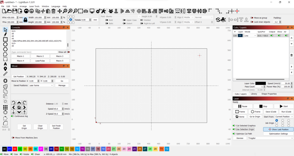
Once the machine is connected to the computer and your work piece has been prepared, the next steps are performed within LightBurn. After launching, the screen should look more or less like this:
1. Asset Import & Preparation – The Canvas
LightBurn is built from the ground up to make laser operation as easy as possible. As such, it supports most 2D vector image formats, as well as most raster image formats for photo engrave operations. For the majority of jobs, you’ll likely be using one of the following recommended formats:
| File Extension | File Format | Vector/Raster | Notes |
|---|---|---|---|
| .lbrn / .lbrn2 | Lightburn Project File | Project File | The most ideal format is Lightburn’s own project format. All information is retained. |
| .ai | Adobe Illustrator Document | Vector | Adobe illustrator files are very well supported in Lightburn and always import to scale automatically. |
| .svg | Scalable Vector Graphics | Vector | SVG is an open source format for vector images. Always double check to make sure your SVG is the right size before starting a job. |
| .dxf | Drawing Interchange Format | Vector | DXF is a proprietary vector format developed by Autodesk. Most templates & designs you can buy are going to be delivered as DXF files. |
| .png | Portable Network Graphics | Raster (Engraving) | PNG files are a lossless image format with support for transparency. If you’re engraving a raster design or photo, use a PNG file if one is available. |
| .jpg / .jpeg | Joint Photographic Experts Group | Raster (Engraving) | JPEG is the most common image file type. JPEGs are often compressed to the point of visible artifacts and may or may not be suitable for engraving. |
Expand for a detailed list of all supported formats in case you need it:
| File Extension | File Format | Vector/Raster | Notes |
|---|---|---|---|
| .lbrn / .lbrn2 | LightBurn | Project File (Vector + Raster + Operation Settings) | The most ideal format is Lightburn’s own project format. All information is retained. .lbrn2 is the same format, just made smaller with lossless compression. |
| .sc / .scpro2 | SignCut | Project File | SignCut is a design software specifically made to facilitate creating signage. Its document format is partially interoperable with LightBurn. |
| .ai | Adobe Illustrator | Vector / Project File (With Raster Support) | Adobe illustrator files are very well supported in Lightburn and always import to scale automatically. Some information may not be retained, but this is unlikely to raise issues. If your .ai file is missing shapes upon import, try applying “Create Outlines” to convert any text to vector shapes. Failing that, try ungrouping shapes. |
| Adobe Acrobat PDF (Portable Document Format) | Vector + Raster (often just raster) | You’ve no doubt encountered many PDF files – they are the de facto format for documents, books, forms, and anything else that’s made to be printed. PDF files are a mixed bag – the format supports both vector and raster content and many different compression algorithms – meaning there’s no broadly excepted standard of quality and low-quality compressed raster photos can sneak in among vector shapes, causing confusion. In addition to this, extra baked-in data such as color profiles, page size, printing & registration marks, and extensive metadata are unlikely to be of any use Illustrator can use PDF files as a project file format by saving with “Preserve Illustrator Editing Capabilities” checked. | |
| .dxf | Drawing Interchange Format | Vector | DXF files are a vector format developed by Autodesk designed for CAD and CAM applications. Many digital assets purchased online will likely be delivered as DXF files. Compatibility issues are unlikely. |
| .svg | Scalable Vector Graphics | Vector (limited raster support) | SVG files are an open source format for vector images and are fully supported by Lightburn. Inkscape uses SVG as its native format. Be certain to double check the scale of all of your objects before running your job – SVG files may not be exactly to scale after import depending on how they were made – Inkscape’s default DPI setting is different from Illustrator’s, and that information is not retained in the format. |
| .gc / .gcode | G-Code | Machine Instructions | G-Code files don’t represent a design – they contain instructions compiled for a specific machine that, when executed, result in the machine creating/cutting out/engraving/otherwise operating based on the shape of a given design. It is possible in some cases to use G-Code to reverse engineer the design they were generated with, but your mileage may vary. Because it does not support more than 30 layers with their own speed and power settings, LightBurn saves the material swatch tests it generates as G-Code rather than its own project format. |
| .nc | netCDF | Machine Instructions | netCDF is a legacy machine-independent data interchange format – in this case, some laser cutters use it instead of G-Code |
| .hpgl / plt | Hewlett-Packard Graphics Language | Machine Instructions | Line G-Code and netCDF, HP-GL is a format used to store machine instructions – specifically plotters. |
| .rd | RDWorks | Machine Instructions | A G-Code like format for laser cutters with RuiDa control boards. |
| .mage | MillMage | Project File/Machine Instructions (?) | An obscure file format used for some CNC software and/or control boards. Documentation is sparse. |
| .bmp | Bitmap | Raster | BMP files are uncompressed image files – perfect preservation of all details, but very large. |
| .jpg / .jpeg | Joint Photographic Experts Group | Raster | JPEG files are the most common image file type – highly optimized, they are as ubiquitous as they are notorious for their distinctive compression artifacts. Your mileage may vary – depending on the image, quality can range from perfectly spotless to irrevocably deep fried. |
| .png | Portable Network Graphics | Raster | PNG files are exceptionally high fidelity, being a lossless image format with support for transparency. If you’re engraving a raster design or photo, use a PNG file if one is available. |
| .gif | Graphics Interchange Format | Raster | GIF files are best known for supporting animations. As a static image format, their limited support for color palette and primitive transparency mean they’re rarely the most ideal choice. |
| .tif / .tiff | Tagged Image File Format | Raster | TIFF is a raster image format often used for printing and reproducing designs and photographs. It is known for high quality and support for a wide range of tagged metadata. |
| .tga | Truevision Advanced Raster Graphics Adapter (TARGA) | Raster | TGA is a legacy raster image format designed for robust support for images saved at different levels of pixel bit depth. It isn’t uniquely useful for laser crafting, but it can be imported if need be. |
| .webp | WebP | Raster | WebP is an oft-misunderstood and not-yet-universally-adopted image format with support for multiple compression algorithms as well as transparency and animation. Many websites have started to deliver most of their images in this format due to its efficiency and the range of features offered. |
There are several ways to import artwork into LightBurn:
- Find the menu bar at the top of the window and navigate to File > Import
- Press CTRL + I (I for Import)
- Drag-and-drop your file into the LightBurn window directly from the file explorer
Doing so should result in your design showing up on the canvas. For the sake of example, this is what LightBurn would show if you imported a file containing one 10cm square:
Once this is done, you’ll want to double check to make sure everything came in at the right size – and that it’ll end up getting cut out in the right place.
The grid in the center of the canvas should generally be looked at as a size reference, not a position reference. Because most jobs will be set up using relative coordinates, the placement of objects on the screen usually doesn’t matter – it’s just a quick visual confirmation that your objects are importing at the right scale.
3. Basic Canvas Navigation & Object Manipulation – Toolbar
The primary method of positioning, scaling, manipulating, and creating objects within LightBurn is to use the tools, located to the left of the canvas by default, to do so directly within the canvas. Before doing so, make sure you know how to navigate the canvas in the first place.
Canvas Navigation
To move the canvas itself around, click and drag with the middle mouse button / scroll wheel.
To zoom in and out, use the scroll wheel. Scroll up to zoom in, scroll down to zoom out. You will find that the position of the mouse controls the point around which the zoom is centered.
The following is a quick summary of the most commonly used tools in the toolbar:
Select Tool
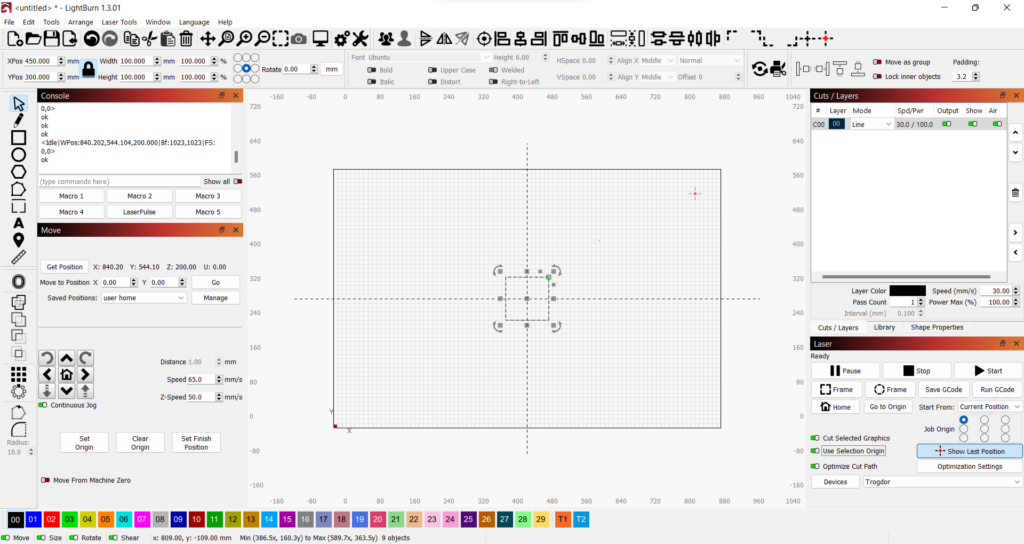
This is the main tool that should be selected most of the time. Use this to select objects by clicking or to move objects by clicking and dragging.
Tips:
- It’s usually most reliable to select objects by clicking along their outline. To select multiple objects this way, hold down Shift or Control.
- You can also “box select” objects like one would it any other graphics software. There’s a twist, though – the direction in which you drag the box matters.
- Dragging from the left performs an “enclosing” selection box in red – when the left mouse button is released, only objects completely enclosed within the resulting box will be selected.
- Dragging from the right performs an “crossing” selection box in green – when the left mouse button is released, any objects that touch the box will be selected.
- If selecting one object selects more objects when you don’t want it to, they may be grouped. If this is not desired, with all such objects selected, press Ctrl+U or navigate to Arrange > Ungroup in the menu bar in order to ungroup them.
Draw Lines
Click multiple spots on the canvas to create a new object comprised of line segments, straight or curved.
- Straight line segments are created by clicking without dragging .
- The current line segment can be made curved by dragging after clicking and holding. This creates a Bezier curve, which can be unwieldy and somewhat counterintuitive. This is recommended only for advanced use or for quick fixes.
- While drawing a shape with this tool, the mouse cursor will adapt to indicate different functions based on the position of the mouse as well as keys held down. Experiment with:
- Snapping points to existing points from other objects
- Increasing the snapping range by holding down the Alt key
- Connecting two open shapes by drawing a line segment between their end points
- Closing an open shape by drawing a line segment between its end points
- Constraining line segments to 45 degree increments by holding down the Shift key
Create Rectangle / Create Ellipse / Create Regular Polygon
These tools are rather self-explanatory. Snapping to points as well as applying proportional constraints are both supported in a similar manner to the Draw Lines tool. Any of these shapes can be created from their center, rather than from a corner, by holding down the Ctrl key. The Regular Polygon tool can create polygons with different number of sides – choose the number of sides in the Shape Properties panel, which is usually paired with the Cuts / Layers panel on the right.
Edit Nodes
Select a shape and activate this tool to be able to drag its points around in order to alter the shape after it has been created.
Create / Edit Text
You can also create text objects, which can be edited after creation. The Text Options panel (usually to the right of the Numeric Edits panel beneath the top toolbar) can be used to adjust the font, font size, alignment, and font styling.
Tips
- Text objects can be used to create LightBurn templates that automatically fill in Variable Text from external data.
- This guide hardly scratches the surface of what LightBurn is capable of. Read the official LightBurn documentation for more info.
4. Precise Positioning & Scale – Numeric Edits, Align, and Nesting
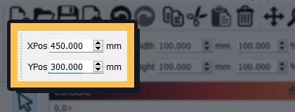
Size and positioning can be checked in several different ways. Next, see the transform controls in the upper toolbar, known within LightBurn as Numeric Edits:
From this, we can see (and adjust) the following:
- The selected object’s current position (at its anchor point, which we’ll go over in a moment)
- Within our Lightburn setup, the lower left corner of the canvas (and work area) is considered (0,0). Increasing an object’s X position moves it further to the right while a higher Y value moves it further back into the work area away from the user.
- During normal use, these position values should not be taken literally – all movements and operations take place relative to the current actual position of the toolhead, not the surface area of the honeycomb as the interface of Lightburn might seem to imply.
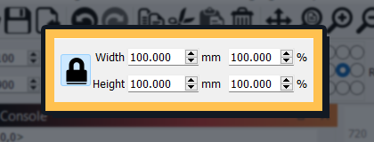
- The selected object’s width and height
- Whether or not the object’s width and height are currently proportionally locked (if resized, the aspect ratio will be maintained with no stretching)
- The selected object’s anchor point
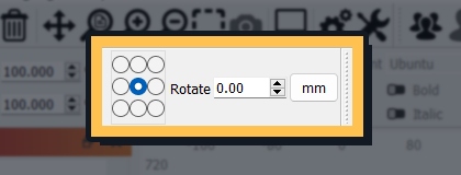
- The current object’s rotation
- The current unit of measurement.
This should be set to millimeters – please refrain from changing this setting as it is likely to invite user error when determining operation settings.
The anchor point of an object is not an immutable property – it simply acts as a point of reference for any information displayed or adjusted in the Numeric Edits panel.
Imagine holding a piece of paper down on a table in the exact center with one finger and rotating it. The position of that finger would be the paper’s anchor point. Now imagine holding it down in the upper left corner and rotating from there. Lightburn allows you to move, scale, or rotate any shape in that way from any of the corners, edges, or the center of its bounding box.
Any of the above information can be adjusted in order to ensure all of your shapes are at the expected scale and arranged as expected in comparison to one another.
4. Tool Head Placement & Focus – “Move” Panel
Once the previous steps have been completed and your design is arranged as desired within the software, you’ll want to use the Move panel within LightBurn to physically navigate the tool head to sit above the an appropriate point over your material – usually a corner or the dead center. Here’s a rundown of all of the movement options you’ll need:
- Directional Arrows
- Distance
- Speed
- Z-Speed
- Contiguous Jog or Incremental Jog
There are other options present, but for basic usage you may ignore them.
Finally, make sure to maximize the quality of your cut and/or engraving by focusing the laser. This is done by measuring the distance between the bottom of the lens and the top of your material.
5. Layers & Cut Settings
The last step before final preparations is to make sure each object in your design is separated into layers as needed, each with cut or engrave settings appropriate for the material.
Sometimes, you’ll need to both engrave and cut an object within one job. To facilitate this, Lightburn offers the ability to separate your job out into color coded “Layers”. These layers, present in the “Cuts/Layers” panel, will be done in order from top to bottom. The color/layer a given shape is assigned to can be assigned via the color palette at the bottom of the window.
In general, there are two kinds of operations within laser cutter operation:
Cut (Line)
.
Engrave (Fill)
.
There is a third option, Offset Fill, but it is only recommended for advanced use.
The most essential settings for both operation types are as follows.
Cut
- Speed
- Power
Engrave
- Speed
- Power / Max Power
- Line Interval
In order to cut down on trial and error, we have compiled a collection of settings presets, located in the Material Library panel, for convenience. To use a preset, navigate to one within the panel, select it, and click “Assign” to apply its settings to the currently selected layer.
If you bring a material we don’t have a preset for, and go through the process of finding optimal settings, please make a preset for it in the Material Library! Check the official docs for more info.
7. Laser Controls
You’re finally ready to get started! Just a few things to check first:
- Select the objects you wish to cut
- Make sure Start From is set to Current Position
- Check that the Job Origin corresponds to the corner, edge, or center of your work piece that the tool head is currently situated above in the machine
- Hit Alt+P or click the Preview button in the toolbar to inspect the tool path and get a rough time estimate
- Use the Rectangle Frame or Rubber Band Frame operations to make sure everything in your job is placed and scaled correctly relative to your material, and to make sure the job won’t result in the tool head attempting to go out of bounds.
- If you find that the tool head is going out of bounds – usually indicated by a loud clanging or grinding noise – turn off the machine with the E-stop immediately.
- Finally, whenever you’re ready, move on to the next section.
